Note: I did most of these projects when I was pretty young. I realize the construction of some of these items is poor and the soldering is not very neat, and in some cases, my building practices were somewhat dangerous (such as soldering directly to a battery), but that’s because I did this all when I was very young.
PCB Flashlights
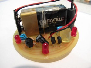
The design of these flashlights was pretty simple. Basically, I took a pre-holed PCB board and stuck the necessary components in, then soldered them to the board. The one shown above was built for catching lightning bugs (the potentiometer could adjust the brightness of the LED to match that of a lightning bug, then I could press the switch to try to mimic the blink pattern of a female).
N-cell Flashlights
First, I started with an N-sized 12v battery. I scratched the battery’s terminals and coated them with liquid resin (to facilitate soldering). I then added solder to the ends of the battery, then soldered an LED’s anode to the positive terminal of the battery. After that, I soldered the LED’s cathode to a push button switch and the other side of the push button switch to a resistor the the negative battery terminal.
Finally, to “water-proof” the device, glue-gun glue was applied generously to form an impromptu case. The result was a quick, bright, throw-away light that was somewhat water-resistant. Note: This was a somewhat more complex variant of these types of flashlights that I made in 5th grade. It still works!
Display Gadget
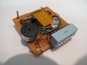
This was probably one of my less thought-out projects. It attempted to combine all sorts of output devices I found interesting at the time. This included a bright white LED, a piezo buzzer, and a 7-segment display. All of these could be turned on via the DIP switch at the bottom.
FM Radio Transmitter
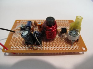
This was one of my attempts at an FM Radio Transmitter. When I had all the components on a breadboard, I was successful in getting a faint signal across about 100 feet to a radio. Unfortunately, the nature of high frequencies is that how well a circuit works is largely dependent on the layout and geometry of the circuit. The FM Transmitter pictured was not very successful in transmitting an input wave.
Electronic Kits
Also when I was young, I had a lot of fun soldering professional electronic kits together. Here’s one such example. The simple board contained two IR sensors on either side of the robot, and a vibrator motor on the bottom. Whenever the robot received an IR signal (from a remote control, for example), the robot would light up and the motor would activate, causing the robot to move.
AGSF Flashlight
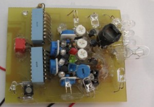
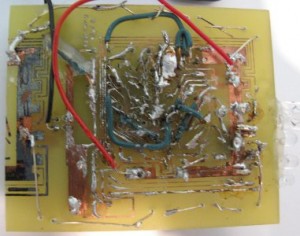
Somewhat following the idea of the Gadget Display, this project focused on incorporating as many different output (and input) devices as possible into one board. At the time, it was actually one of my most advanced projects, for several reasons. First, it incorporated a variety of sensors. From the image, you can see in the middle of the board, a red, green, and blue filter on top of some photodiodes. The LEDs next to those diodes lighted up depending on the light incident on the photodiodes. Another reason this board was advanced is that it contained an RGB output device (the part with black paper). You could vary the potentiometers to vary the output levels of red, green, and blue. The board also contained other output devices – IR, UV, and White LEDs (as well as an incandescent light). All of these could be controlled by the DIP switches on the left.
However, one of the main advances of this board was that the PCB was completely designed by me. What I did was design the PCB in PowerPoint, then the design was printed onto photo paper using a laser printer. The toner was transferred onto a copper clad board by ironing, then, because I was only 10 years old, my dad etched the board with Ferric Chloride for me. After cleaning the board a bit to remove the excess toner, I ended up with the final result – this board. Later, in many of my more advanced projects, I would use this technique to create custom circuit boards.


