Oscilloscope Circuit
Finally, putting everything together completed the oscilloscope circuit. The parts required were:
- MC6802 MPU
- OKI 28C16A ROM
- (3) LS373 Latch
- LS183 Decoder
- 0804 ADC
- LCD Display
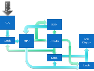
And combining the ADC circuit with the LCD circuit yielded the following flow chart:
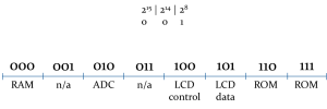
Before wiring everything up, I needed to decide what addresses would map to what peripherals. So I created an address map:
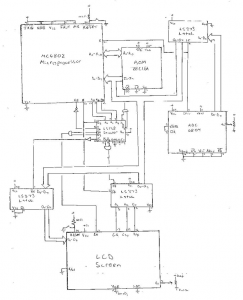
With this finished, the schematic diagram was not too difficult to create:
Unfortunately, as I mentioned above, I couldn’t get the LCD to function properly. no matter what program I used, it seemed to output garbage. Regardless, here’s the final code I used (although it still didn’t operate the LCD properly).
;===============================================+
;	Albert Gural								|
;	05/31/11									|
;	Analog to Digital to LCD Display Output		|
;	To Create a Simple Oscilloscope				|
;===============================================+

ADC		= $$4000				; Analog to Digital Convertor
LCDC	= $$8000				; LCD Control Pins (Data: {0: D/I, 1: CS1, 2: CS2})
LCDD	= $$8100				; LCD Data Pins (Data: {x: x})
LCDG	= $$0100				; LCD to latches (enact latches on LCD)

			.area MAIN (ABS)
			.org	$$0100

main:							; Start of Program
			LDS		#$$007F		; Set start address of the stack

init:							; Set up the LCD
			; Turn On Monitor
			LDAB	#$$02		; load 0000,0010
			LDAA	#$$3F		; load 0011,1111
			STAB	LCDC		; set lcd to data/CS1
			STAA	LCDD		; store in data latch

			; Display Start Line
			LDAA	#$$C0		; load 1100,0000
			STAA	LCDD		; set lcd data

			; Set Page (X)
			LDAA	#$$B8		; load 1011,1000
			STAA	LCDD		; set page 0

			; Set Address (Y)
			LDAA	#$$40		; load 0100,0000
			STAA	LCDD		; set address 0

			; Reset data
			LDAA	#$$00		;
			STAA	LCDD		; set data to 0

			; Set LCD in write mode
			LDAA	#$$03		; load 0000,0011
			STAA	LCDC		; turn LCD to write mode

loop:							; Continuously put ADC into LCD
			LDAA	#$$40		; load 64
loop2:		LDAB	#$$AA;ADC			; Take data from the ADC
			STAB	LCDD		; Store it in the LCD's Data
			BSR		pause		; pause for a small amount of time
			DECA				;
			BEQ		endloop		;
			BRA		loop		; loop
endloop:	LDAA	#$$00		; generic operation
			BRA		endloop		; infinite loop end

pause:		LDAB	#$$FF		; Count down from FF
p2:			DECB				;
			BEQ		p3			; If == 0, branch to return
			BRA		p2			; else loop
p3:			RTS					;
Conclusion
I was successful in getting many peripherals working with the MPU, but the LCD didn’t seem to want to cooperate. Maybe if I’d had a bit more time, I could have gotten it working.
In any case, I need to thank several people for their help on this project. My partner was Sarah, who helped with a lot of documentation as well as circuit wiring. Nick and Ned were two students in the class who knew way too much about electronics. Their suggestions and help were invaluable. Finally, thanks to Mr. Montgomery and Mr. Bell, the two lab directors/teachers for this course.
Also, this was a class project, so an associated presentation exists:


