At first I was pretty sure I had made a mistake in my charlieplexing, so I scoured over the schematic diagram to make sure everything was wired correctly. I even produced a simple simulation on this java-based electronics simulator. All of these seemed to point to me having no wiring error in the circuit. So I thought maybe the circuit board I had made was bad. I tested, for example, resistances between the I/O pins to see if this would illuminate any errors. It didn’t really; in fact, I’m not even sure how much good data you can get from measuring the resistance across microcontroller pins.
If you’re interested in seeing the “theoretical” Charlieplexed schematic, you can see a simulation I created using Falstad’s circuit simulator.
By this time I had been fussing around for about a half hour, so I decided to systematically document which LEDs lit up as I sequenced through the LEDs in the program. At first, it all seemed random, but I knew it couldn’t be since the same pattern happened again and again. So I finished systematically figuring out what intended output led to what actual output. At first, it didn’t make much sense, but then I noticed something. If, Instead of an LED at LED2, I had a wire, then LED4 and LED5 would light up. But wait, so would LED7 and LED8. Ah… not if instead of the wire I had a backwards-diode! Then, LED4 and LED5 would light up but not LED7 and LED8!
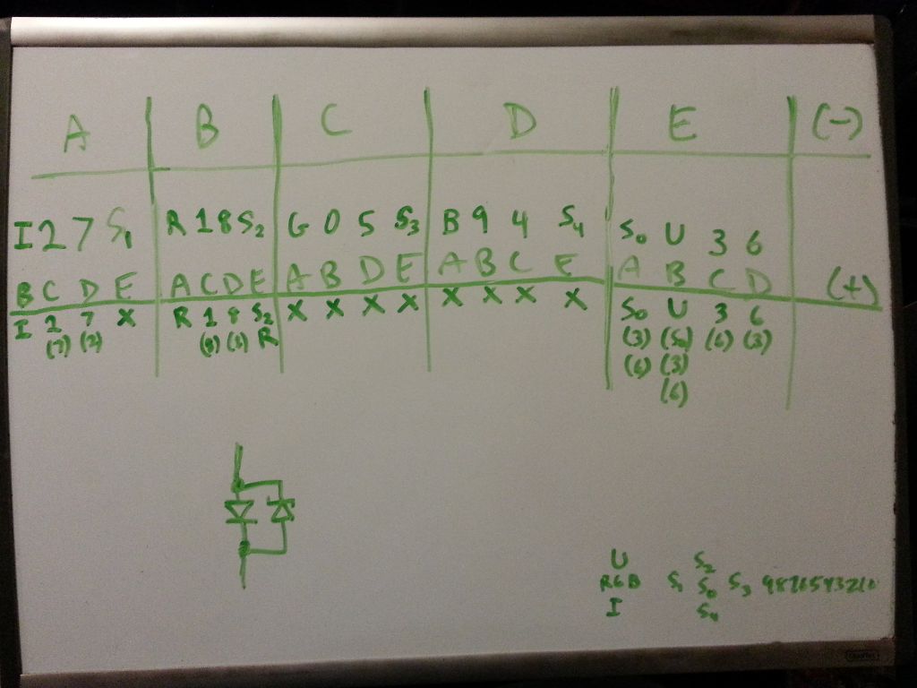
Systematically comparing desired and real behavior.
In fact, when I added backward-biased diodes to a few of the LEDs, a lot of the patterns I was seeing made sense. So I started figuring out exactly which LEDs needed the backward-biased diodes, and I realized that it was only the blue LEDs that needed it. When I added backward-biased diodes to the blue LEDs in the schematic, the theoretical behavior eactly matched reality! So that must mean that the blue LEDs I ordered had back-biased diodes in them.
Here’s the problematic circuit, again using Falstad’s circuit simulator.
I checked the LED data sheet, and sure enough, they had an “reverse voltage protection diode” connected just as I had suspected. So I ordered non-“protected” blue LEDs, and replaced the blue LEDs on my board, and everything started working! I guess this experience really taught me the importance of really looking at the part datasheet. It also taught me that when encountering a bug, it’s important to really understand exactly what the symptoms are. I wasn’t able to figure out the problem until systematically documenting everything that was wrong with the charlieplexed system.